Hi to the TCA fans, and thanks for checking out my spot.
The big question was finally asked...why?
An admirable query to be sure.
There are a couple of reasons. Most of all, for a geek like me the oportunity to build my own robot was too exciting to pass up. On that line of thought the idea of being able to build something no one else has yet mastered is almost more exciting than having a whole block of chocolate all to myself. Almost.
The personal reasons for accepting the invitation to tackle this project are actually rather boring though. I found when I had a year off study (the first since i started school, age 5) that I lost interest in a lot of things. By not having something that was keeping my brain busy I was losing the motivation to keep it busy myself. In short I was getting bored. The geek factor was big, and another draw card was the fact that I was jumping from second year diploma level to third year degree level by invitation. Who could turn down such an ego trip, honestly? The Air Force would pay me back every cent of the cost of the paper, as long as I proved it was work related and as long as I passed the course. Free education rocks. And it looks good on my service record. It looks good on my personal file and my CV if I ever make one. The time management and research skills alone would pump my CV to overfull. There are many pro's.
As to why a robot which does nothing more than balance? When I have explained to others I am involved in a project to build a balancing robot, they ask me - "So what does it do.?" And I reply "It balances." I don't think many people really comprehend the sheer processing power reqiured to stop this puppy from falling over. These four processors will be working at speeds of 8MHz, that means it carries out a seperate complete instruction every 125 nano seconds. Even so, I am unsure it will be fast enough.
Our supervisor has chosen a project that requires an immense amount of processing power because once we have completed it he will improve on it. He will remove our standardised and interchangeable daughterboard (with an Atmel ARM computer processor on it) and replace it with a similar board which uses FPGA technology.
I'm not sure I should go down this track or I might be typing all night. The more a person knows about digital technology the easier it is for me to explain, so I imagine it will be best not to get too technical. Let's look at it this way;
A standard processor is filled with little sub systems - counters, timers, analogue to digital converters (ADC's), communications systems, input and output ports, real time clocks, and all sorts of other miniscule gadgets. A programmer reads through the manual and learns how to use programming code to turn on and off these subsystems, controlling them and saving values for later use to get the results we want. To balance this robot, my lab partner and I will program the chip to turn on an ADC, process the gyro input and save it. This will be repeated with the other gyro. Then the program instructs the processor to filter and error-check the inputs. The new values are saved, collated and sent via a 'series communications' subsystem up to the daughterboard. The processor on the daughterboard is programmed to receipt these values and carry out the mathematics, then return the values.
Every move must be covered by us, the programmers. We control, through our code, every subsystem within the processor.
FPGA.
Field Programmeable Gate Array.
An FPGA has no subassemblies. It is an array of switches which can be turned on or off to form pseudo systems. My supervisor took a plain FPGA chip and set it up so that within that one physical device there were two - two - pentium processors. There was plenty of room left for more devices. It's technical but trust me when I say using switches makes FPGAs very fast too.
Now, we can run conventional coding techniques through FPGA's. We can set them up to contain all those sub-systems and then program it as I detailed above. Or we can get a computer to run evolutionary programming.
We give the computer a set of parameters.
"In a five minute period, the robot must not fall over."
The computer blasts the blank FPGA with a random sequence of ones and zeros. Computer runs the robot and the robot immediately falls over. So the computer deletes half of the random code, replaces it with a new random code and tries again. Again the robot falls over. After trying this for a few hundred generations, the FPGA manages to send a message to spin the motors and the robot doesn't fall over until three seconds have passed. The program has been improved.
The computer keeps the good code and scraps the rest, generating more random binary until perhaps the motors move at a better speed or in unison or until the sensors are being read and filtered and corresponding instructions are being sent to the motors. We are talking millions of generations of code, hopefully only taking steps forward - evolving. The computer will keep working until the robot balances on its own for five minutes.
All the programmer has to do is enter in the initial parameters and monitor the progess. And on top of that; once it is complete the FPGA is extraordinarily efficient at running the program and faster than comventional processors.
Back to the initial question - why?
Why? Ultimately to display the enormous processing power of FPGA's and the advantages of the 'evolutionary programming' technique. And yes, a droid will appear from the future to kill my supervisor. But not me because I'm not taking the FPGA paper next year, though I would like to.
I hope that answers the question?
Tuesday, September 05, 2006
Sunday, September 03, 2006
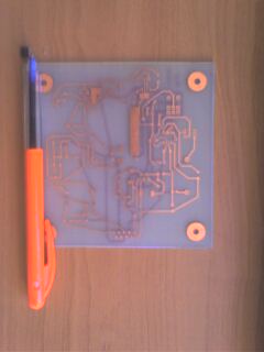
The Power supply board has finally been manufactured and now we have to 'populate' the board with components and make sure everything is working right. We're still waiting on one type of microchip to arrive from the suppliers and a...contact...of mine is arranging to have our batteries made to the perfect specification. Here's a look at just how small the board and some of the components are:

The dimensions of the board are 100mmx100mm (that's just under 4 inches square). The photo on the right has zoomed in a little on the components which we will be populating the board with. The microchip I have placed over its pads in the board, just to the left of the pen. Within the red circle is a surface mount capacitor. This is so small it came out too fuzzy to see, but it's roughly a 16th of an inch long and half again as wide. TINY! Thank goodness I don't have to get a soldering iron into that. The program which has helped me design this whole project will also generate what is called a 'pick and place' file. This can be entered into another type of robot which will place the capacitor and other surface mount components onto the board in the right place. There will already be a layer of solder plaste on the pads and the board is then heated in an oven. The solder melts then sets and presto! the components are in place without me having to go anywhere near them!

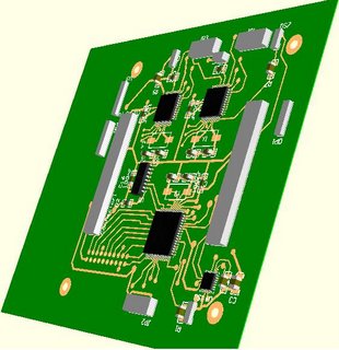
Just as another bit of interest - I explained how the footprints work that allow the program to know how many pins etc a component has. Well a lot of footprints also detail the height and shape of the part as well and DXP can generate a 3D image of what the PCB will look like once it is made. Here's a 3D image of the processor board. The large square microchip has 128 pins coming out all four sides and those pins are as little as the ones on the micro in the pictures above. Using the 3D feature has been extrememly helpful for me to visualise how the boards will mate together - the grey rectangles are connectors and they fit into more printed circuit boards. At the moment the robot will require four or maybe five of these boards and four processors just to get the job done. Wish me luck!


The dimensions of the board are 100mmx100mm (that's just under 4 inches square). The photo on the right has zoomed in a little on the components which we will be populating the board with. The microchip I have placed over its pads in the board, just to the left of the pen. Within the red circle is a surface mount capacitor. This is so small it came out too fuzzy to see, but it's roughly a 16th of an inch long and half again as wide. TINY! Thank goodness I don't have to get a soldering iron into that. The program which has helped me design this whole project will also generate what is called a 'pick and place' file. This can be entered into another type of robot which will place the capacitor and other surface mount components onto the board in the right place. There will already be a layer of solder plaste on the pads and the board is then heated in an oven. The solder melts then sets and presto! the components are in place without me having to go anywhere near them!

Just as another bit of interest - I explained how the footprints work that allow the program to know how many pins etc a component has. Well a lot of footprints also detail the height and shape of the part as well and DXP can generate a 3D image of what the PCB will look like once it is made. Here's a 3D image of the processor board. The large square microchip has 128 pins coming out all four sides and those pins are as little as the ones on the micro in the pictures above. Using the 3D feature has been extrememly helpful for me to visualise how the boards will mate together - the grey rectangles are connectors and they fit into more printed circuit boards. At the moment the robot will require four or maybe five of these boards and four processors just to get the job done. Wish me luck!
Subscribe to:
Posts (Atom)