It certainly has been a while since I've updated the page, but in all fairness I've been pretty busy with other things.
The end of the year has finally descended upon us and it was only last Friday we had to hand in our final project reports for Libramentum.
Unfortunately we never got the poor robot up and running but we have been granted the oportunity to continue working on it so that there will be something to show for our efforts. I have included here some extracts from my report.
Abstract
The project is to design a robot capable of balancing dynamically on a sphere. This is an expansion on a previous inverted pendulum project, and had provision for the development of additional operations.
The previous project was a Mobile Inverted Pendulum design (BBot, [names supplied], AUT 2005) and involved stabilising a pendulum which had two planes of free rotation, such as the popular product ‘Segway.’ This project; undertaken by [names supplied], has an additional plane of freedom, creating a robot that could fall in any of 360 degrees. The design involved taking the design concept of BBot which could fall forwards or backwards, and advancing the systems to control and stabilise a pendulum on a sphere.
The project consisted of adapting the BBot inertial angle measurement system which calculates the speed and angle of fall and designing the systems required to stabilise the platform. Interchangeability was a strong design commitment; the robot would have to be able to accept several different daughterboards enabling advanced programming techniques to be implemented including evolutionary programming.
Concept and Motivation
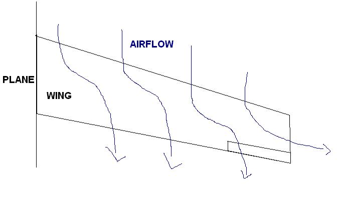
A machine which is statically stable, such as a three or four wheeled robot, is able to balance at all times. ‘At all times’ encompasses whilst moving, unmoving, and during a power-down state. While this is convenient for the greater part of the time, problems arrive when the machine which is usually stable begins to lose its stability. In the case of a knock or fall the machine is susceptible to damage from an inability to prevent its fall. Our robot overcomes this concern by containing a system dedicated to balance one hundred percent of operation time. While this means power and processing time will be consumed keeping the pendulum balanced under no other force than gravity, it also means that it will be resistant to and able to recover from other external forces as well, where a more conventional machine might not.
Previously, a robot known as BBot was developed by AUT students. BBot is an inverted pendulum which could fall backwards or forwards, but has sensors and systems in place to keep it in an upright position. At the bottom of the pendulum is an axel and two wheels which are each driven by a motor. These motors are not only responsible for driving the robot across a surface, but also for its dynamic balance.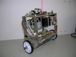
Fig 1A
In order for this design to move in a different direction it must first turn. This requires space and possibly substantial time to execute. By transposing the concept onto a sphere, changing the direction of movement is only a matter of driving a different combination of motors (software will need to keep up with the balancing requirements here). This makes the new design more compact and manoeuvrable
Like its predecessor BBot, our robot is a platform which facilitates various forms of processor and software. It has room for advancement in station keeping and remote control. It will be a processor intensive platform which has the potential to demonstrate the power of FPGA technology and evolutionary programming.
There is not a great deal of previous experience available regarding a pendulum which has successfully been balanced on a sphere, as we propose to do. While projects involving inverted pendulums are scattered all over the internet, there seem to be only a few involving a robot balanced on a ball. One of these projects is ‘Ballbot,’ by Microdynamic Systems Laboratory. They have designed and built a robot the height of a human which balances and moves on a single sphere.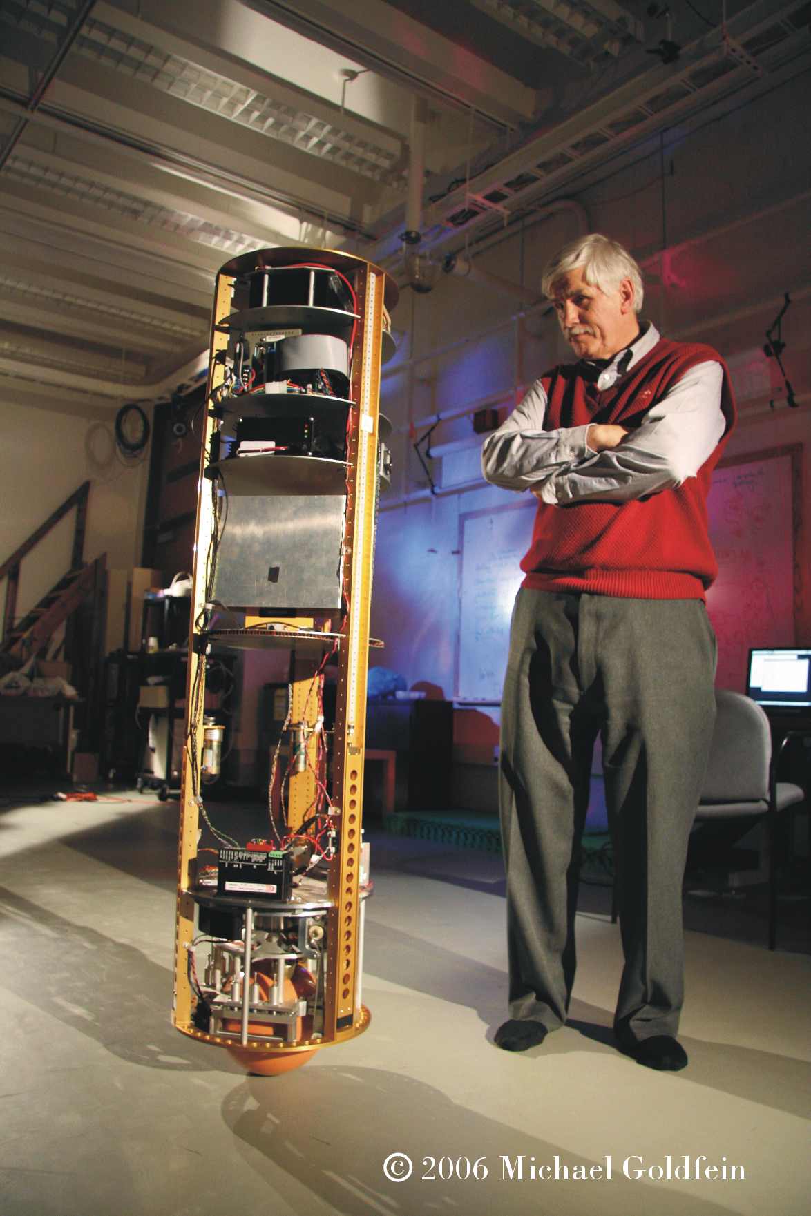
The robot shown is large and bulky and looks difficult to transport. We wanted a compact design which could be easy moved around and taken to other locations with minimum fuss. With the ability to interchange between different main processing units we could in the future install a system such as Bluetooth and run advanced functions from the likes of a laptop computer. This means a lot of hardware doesn’t have to be physically located on the robot, enabling small design and portability without reducing the capability .
Fig1B
http://www.msl.ri.cmu.edu/projects/ballbot/
On the surface our robot wouldn’t have any practical purpose, but it would certainly be an invaluable tool to AUT. A primary concern is flexibility and the hardware must include provision for interchangeability. The ability to change the daughterboard allows for upgrading and refining the software, advancing the features and introducing new features as technology grows. All these possibilities have room for research and projects within AUT itself which makes it a worthwhile design. In addition, these same functions also mean the robot could eventually be developed into a machine which has a practical purpose outside of the university environment, which is definitely a positive motivation.
That's all I have for now, but stay tuned as I will go through our post-paper work with you and am going to try and get some photos of the structure of Libramentum as she has been created thus far.