Hi to the TCA fans, and thanks for checking out my spot.
The big question was finally asked...why?
An admirable query to be sure.
There are a couple of reasons. Most of all, for a geek like me the oportunity to build my own robot was too exciting to pass up. On that line of thought the idea of being able to build something no one else has yet mastered is almost more exciting than having a whole block of chocolate all to myself. Almost.
The personal reasons for accepting the invitation to tackle this project are actually rather boring though. I found when I had a year off study (the first since i started school, age 5) that I lost interest in a lot of things. By not having something that was keeping my brain busy I was losing the motivation to keep it busy myself. In short I was getting bored. The geek factor was big, and another draw card was the fact that I was jumping from second year diploma level to third year degree level by invitation. Who could turn down such an ego trip, honestly? The Air Force would pay me back every cent of the cost of the paper, as long as I proved it was work related and as long as I passed the course. Free education rocks. And it looks good on my service record. It looks good on my personal file and my CV if I ever make one. The time management and research skills alone would pump my CV to overfull. There are many pro's.
As to why a robot which does nothing more than balance? When I have explained to others I am involved in a project to build a balancing robot, they ask me - "So what does it do.?" And I reply "It balances." I don't think many people really comprehend the sheer processing power reqiured to stop this puppy from falling over. These four processors will be working at speeds of 8MHz, that means it carries out a seperate complete instruction every 125 nano seconds. Even so, I am unsure it will be fast enough.
Our supervisor has chosen a project that requires an immense amount of processing power because once we have completed it he will improve on it. He will remove our standardised and interchangeable daughterboard (with an Atmel ARM computer processor on it) and replace it with a similar board which uses FPGA technology.
I'm not sure I should go down this track or I might be typing all night. The more a person knows about digital technology the easier it is for me to explain, so I imagine it will be best not to get too technical. Let's look at it this way;
A standard processor is filled with little sub systems - counters, timers, analogue to digital converters (ADC's), communications systems, input and output ports, real time clocks, and all sorts of other miniscule gadgets. A programmer reads through the manual and learns how to use programming code to turn on and off these subsystems, controlling them and saving values for later use to get the results we want. To balance this robot, my lab partner and I will program the chip to turn on an ADC, process the gyro input and save it. This will be repeated with the other gyro. Then the program instructs the processor to filter and error-check the inputs. The new values are saved, collated and sent via a 'series communications' subsystem up to the daughterboard. The processor on the daughterboard is programmed to receipt these values and carry out the mathematics, then return the values.
Every move must be covered by us, the programmers. We control, through our code, every subsystem within the processor.
FPGA.
Field Programmeable Gate Array.
An FPGA has no subassemblies. It is an array of switches which can be turned on or off to form pseudo systems. My supervisor took a plain FPGA chip and set it up so that within that one physical device there were two - two - pentium processors. There was plenty of room left for more devices. It's technical but trust me when I say using switches makes FPGAs very fast too.
Now, we can run conventional coding techniques through FPGA's. We can set them up to contain all those sub-systems and then program it as I detailed above. Or we can get a computer to run evolutionary programming.
We give the computer a set of parameters.
"In a five minute period, the robot must not fall over."
The computer blasts the blank FPGA with a random sequence of ones and zeros. Computer runs the robot and the robot immediately falls over. So the computer deletes half of the random code, replaces it with a new random code and tries again. Again the robot falls over. After trying this for a few hundred generations, the FPGA manages to send a message to spin the motors and the robot doesn't fall over until three seconds have passed. The program has been improved.
The computer keeps the good code and scraps the rest, generating more random binary until perhaps the motors move at a better speed or in unison or until the sensors are being read and filtered and corresponding instructions are being sent to the motors. We are talking millions of generations of code, hopefully only taking steps forward - evolving. The computer will keep working until the robot balances on its own for five minutes.
All the programmer has to do is enter in the initial parameters and monitor the progess. And on top of that; once it is complete the FPGA is extraordinarily efficient at running the program and faster than comventional processors.
Back to the initial question - why?
Why? Ultimately to display the enormous processing power of FPGA's and the advantages of the 'evolutionary programming' technique. And yes, a droid will appear from the future to kill my supervisor. But not me because I'm not taking the FPGA paper next year, though I would like to.
I hope that answers the question?
Tuesday, September 05, 2006

Sunday, September 03, 2006
The Power supply board has finally been manufactured and now we have to 'populate' the board with components and make sure everything is working right. We're still waiting on one type of microchip to arrive from the suppliers and a...contact...of mine is arranging to have our batteries made to the perfect specification. Here's a look at just how small the board and some of the components are: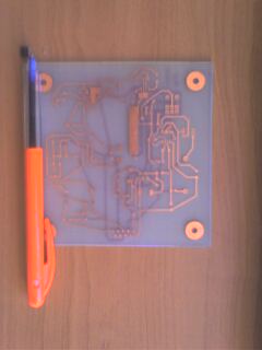

The dimensions of the board are 100mmx100mm (that's just under 4 inches square). The photo on the right has zoomed in a little on the components which we will be populating the board with. The microchip I have placed over its pads in the board, just to the left of the pen. Within the red circle is a surface mount capacitor. This is so small it came out too fuzzy to see, but it's roughly a 16th of an inch long and half again as wide. TINY! Thank goodness I don't have to get a soldering iron into that. The program which has helped me design this whole project will also generate what is called a 'pick and place' file. This can be entered into another type of robot which will place the capacitor and other surface mount components onto the board in the right place. There will already be a layer of solder plaste on the pads and the board is then heated in an oven. The solder melts then sets and presto! the components are in place without me having to go anywhere near them!
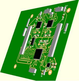
Just as another bit of interest - I explained how the footprints work that allow the program to know how many pins etc a component has. Well a lot of footprints also detail the height and shape of the part as well and DXP can generate a 3D image of what the PCB will look like once it is made. Here's a 3D image of the processor board. The large square microchip has 128 pins coming out all four sides and those pins are as little as the ones on the micro in the pictures above. Using the 3D feature has been extrememly helpful for me to visualise how the boards will mate together - the grey rectangles are connectors and they fit into more printed circuit boards. At the moment the robot will require four or maybe five of these boards and four processors just to get the job done. Wish me luck!
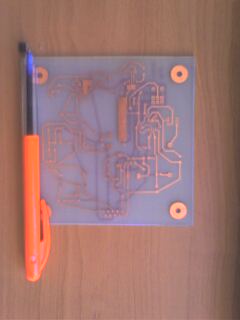

The dimensions of the board are 100mmx100mm (that's just under 4 inches square). The photo on the right has zoomed in a little on the components which we will be populating the board with. The microchip I have placed over its pads in the board, just to the left of the pen. Within the red circle is a surface mount capacitor. This is so small it came out too fuzzy to see, but it's roughly a 16th of an inch long and half again as wide. TINY! Thank goodness I don't have to get a soldering iron into that. The program which has helped me design this whole project will also generate what is called a 'pick and place' file. This can be entered into another type of robot which will place the capacitor and other surface mount components onto the board in the right place. There will already be a layer of solder plaste on the pads and the board is then heated in an oven. The solder melts then sets and presto! the components are in place without me having to go anywhere near them!
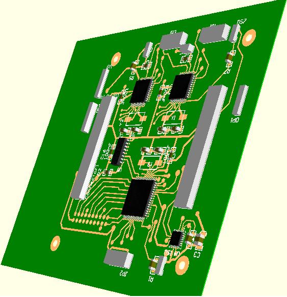
Just as another bit of interest - I explained how the footprints work that allow the program to know how many pins etc a component has. Well a lot of footprints also detail the height and shape of the part as well and DXP can generate a 3D image of what the PCB will look like once it is made. Here's a 3D image of the processor board. The large square microchip has 128 pins coming out all four sides and those pins are as little as the ones on the micro in the pictures above. Using the 3D feature has been extrememly helpful for me to visualise how the boards will mate together - the grey rectangles are connectors and they fit into more printed circuit boards. At the moment the robot will require four or maybe five of these boards and four processors just to get the job done. Wish me luck!
Thursday, August 17, 2006
Moving Again
FINALLY! My Printed Circuit board design has been accepted by the techs, and is now in the lab for manufacture. All I have to do now is wait for it, and wait for a few more parts then we can solder the components in place and begin the hardware testing. My lab partner and I are also working on those structure diagrams for the programming.
Tuesday, August 08, 2006
Things are looking a little down at the moment. I'm a little stressed, with a course at work I have to study for every night and less than a week (four days even) to completely redo my PCB as apparently it wasn't good enough. Arrrrrgh! I have no more time. We're a bit behind, but watch this space and see me catch up ;-)
Saturday, August 05, 2006
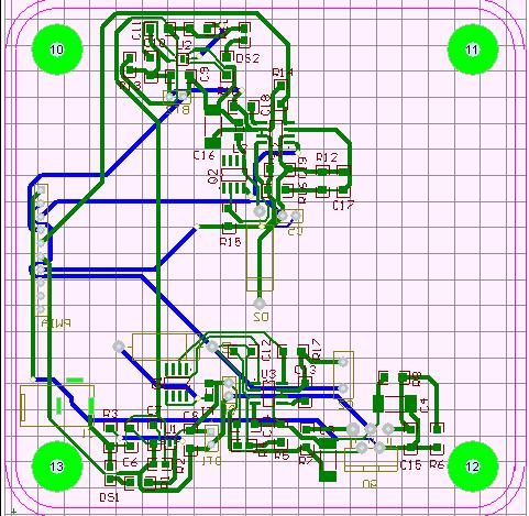 Ta Daaaa! There it is, the finished PCB layout. Well actually this is only one of the finished products. There are a couple more as well! All we have to do now is have those boards manufactured and we can get into testing them to make sure they work. The best way to do this will be to program the processors with basic routines which will operate each sensor one by one. Then if and when the code fails we will be able to use a process of elimination to work out what needs to be fixed or replaced. These things will never work first time.
The next step is the software and my lab partner and I are already beginning to look into it. As with all missions, this one requires a plan and one of the most effective way to plan a program is to use a structure diagram. There are two methods for drawing the program into a diagram - a flow chart or the use of case statements. I won't go into case statements because at the moment that's not the design format we are using. I will include a very basic flow chart which breaks down the interaction between the parts of Libramentum. Although I would like to (because it is very exciting) I won't go into great detail about the coding structure because I don't particularly want it stolen and to
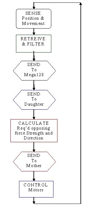 be honest - I don't trust this internet thungimajig! So here is a very basic idea of what the program will be doing. This is a cut and paste from a word document flow diagram. First we want the sensors to do their job of working out what is going on, then the two minor processors on the motherboard will (between them) filter that information and send values to the main processor - here labelled the Mega128. From there the [Atmel AT]Mega128 will turn the voltages and codes into a discrete set of values. These values will be sent to the daughterboard which has an Atmel ARM processor on it. This processor does all the hard yards - it does all the complicated maths that will turn those values into an understanding of exactly what is happening to the robot. Additionally it calculates what force will be required at each of the three motors (and in which direction!) and sends these values back to the motherboard - the one we started on - who sends the correct voltages through special control circuits called H-bridges to the motors. As soon as it's set the H-Bridges it immediately collects the next lot of sense information - even as the motors are busy righting the robot!
Now as I said - that flow diagram was thrown together using Microsoft Word, but there are special symbols used by programmers. There are many different ways of writing a program and you might hear about all sorts of 'languages,' Pascal, C-Plus, Java, Pearl and others. The special thing about a structure diagram is that it can be written by someone with only a basic understanding of a single language, and any program developer anywhere should be able to pick it up and write a program in any language that will do what the structure describes. It is a plan of how the overall system is handled. The details are for the individual to work out for themselves. I felt guilty about not putting any of the diagrams for Libramentum up, so I'll put up another instead. I made this in about 30 seconds, and will see what I can do about coding it later...

It's a little difficult to see, and I apologise, but lets look at what it says.
** START (easy)
** IF you are a boy. This is an 'IF/ELSE' statement. If the statement is true take the action from the right of the diamond - Go to the Rugby. If the statement is false, take the action from the bottom of the diamond - Go to the netball. Once these have been completed, we return to the next action after the 'IF' box.
** FOR the duration of the game. This action has a loop on it and the little equals sign indicates where the test is carried out. The program 'tests' the for statement, while the game is being played, the program will carry out any actions attached to that loop - in this case, obey the ref. when the game is no longer in progress the FOR statement will be false and the program will break out of the loop. We could add another simple action after the FOR loop which instructs the program to "go to the aftermatch function." When the program reaches END it knows it has nothing more expected of it and will not look for further instructions. So you can see from that diagram that there was no actual code included in it. The words in the box were on the whole simple english, designed to be picked up by anyone and turned into a program. This is important because there will be three people working on the code for Libramentum. My Lab partner and I have designed a lot of little programs before and we have a good system going. I predict that for the software design of this robot we will work at it seperately and then work out which design to turn into code. Often we'll create an amalgamation of the two designs. It is important we are able to pick up the other persons structure and be able to almost immediately see what the other is intending. Also, our supervisor needs to be able to keep an eye on our progress and add his input, which is quicker and easier for all if we don't spend half an our explaining what we mean in our plan.
So if you're still interested keep reading and I'll try and turn my spontaneous structure diagram into some C-code.
#include
#include
#define boy 1
#define girl 0
#define rugby 1
#define netball 0
void main(void)
{
int person=boy, game, rugby, netball, obeyRef, gameTime;
if(person == boy)
{
game = rugby;
}else
game = netball;
gameTime = 1200;
for(gameTime > 0)
{
obeyRef = 1;
gameTime--;
}
}
It's a lot harder to read isn't it? In fact, if you don't know programming, or if you haven't worked with anything that works like C then the whole thing is a lot of gibberish. That's why the structure diagram is so important - because it's universal. I don't know if some of you reading this have much experience with programming, but I bet anyone you know who does will be able to take my structure diagram and turn it into code. But that code might look very different to mine. And I know some people reading this will have as much AND more experience at programming than me and will probably be shaking their heads at this awful mashed example, but I would like to take this oportunity to point out that I whipped up in only a few minutes because my flatmates are putting on a DVD and I want to see it. Ciao!
Friday, July 28, 2006
Time Drags
Things seem to have slowed down a little as we come to the end of our PCB design. (See previous post for a break down). There are a few little niggly things that need to be sorted and then hopefully all will be ready for manufacture. We are having a couple of issues with the footprints as some need to be manually designed on the computer and this means we have to find the supporting documentation that will allow us to get it right. But as I said we are nearly there.
From here we are beginning to look at the software side of things and this is a lot more interesting as far as I am concerned. There are three processors on the mother board and another on the daughterboard that need to be programmed and a lot of the code will be... how to explain?
Lets say you want to play a game of Cluedo. You get out the board, pick who plays which character, sort the cards and pick out the murder pack, shuffle, deal, and finally begin the game. Programming a proccessor is similar in that you have to organise the program before it can begin doing it's thing. There are a lot of ones and zeros which must be used to turn on certain functions and set operating parameters. It can be hard, but only if you don't know what to look for and this side of things comes with experience. The manufacturers supply pretty detailed instructions anyway :-)
So the next chapter in the saga is a move from hardware to software, but the going doesn't get any easier. More later.
From here we are beginning to look at the software side of things and this is a lot more interesting as far as I am concerned. There are three processors on the mother board and another on the daughterboard that need to be programmed and a lot of the code will be... how to explain?
Lets say you want to play a game of Cluedo. You get out the board, pick who plays which character, sort the cards and pick out the murder pack, shuffle, deal, and finally begin the game. Programming a proccessor is similar in that you have to organise the program before it can begin doing it's thing. There are a lot of ones and zeros which must be used to turn on certain functions and set operating parameters. It can be hard, but only if you don't know what to look for and this side of things comes with experience. The manufacturers supply pretty detailed instructions anyway :-)
So the next chapter in the saga is a move from hardware to software, but the going doesn't get any easier. More later.
Friday, July 21, 2006
Green Square thing with Shiny bits
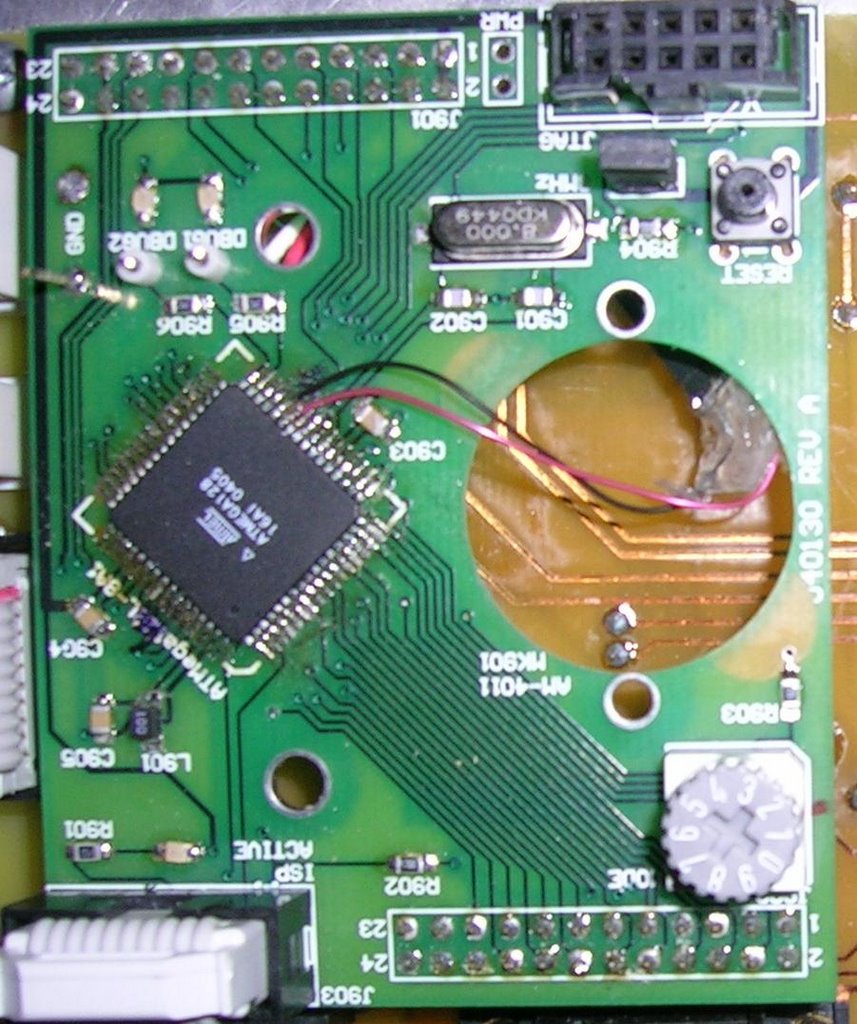
Yeah, in geek speak it's a PCB which stands for Printed Circuit Board. It's the green board you see when you open up your tv or computer. We have to make a few to get Libramentum up and running, and they have to be done by Tuesday. Let me take you through the process.
When we choose the components we want, like which processors and which accelerometers, they come with a data sheet that detail everything you need to know to get the thing running and how to extract the information. It'll tell you things like the maximum and minimum voltage levels, maximum current draw and where to put all the little resistors and capacitors that you see around a microchip. With this information we can get to work and start making electrical schematics to show how the electrons are going to make it from chip to chip. Schematics: Completed.
We're now coming to the end of the hard part. This is where we look up every single individual component and order it, as well as recording the details of the size and shape so that we know where to put the holes and the solder pads on the PCB. We save this information against each component on the schematic. It's not hard - until you can't find a source for the part you want, or the dimensions are not already in the library of 'footprints' and we have to make them up ourselves. This won't make any sense to anyone who isn't into this sort of geeky stuff, but I'll come back later and load some pictures to show you what I mean.
Once we have a footprint loaded against each component on the scematic we can run a program which places each footprint on a digital PCB. Then we can simply click and drag to get them all fitting on the outline and try to place them so that the solder tracks won't have to cross each other. From there we can run the "Auto-route" and the computer will try to connect all the pins up itself. If there are contentions, then that's for us to sort out and that's the hard part. My lab partner and I have been working on these PCBs for several weeks now and we're starting to get really sick of it!
Okay, here's a breakdown with images of the design process. I'll use images from the power supply so as not to compromise our intellectual copyright (as it were).
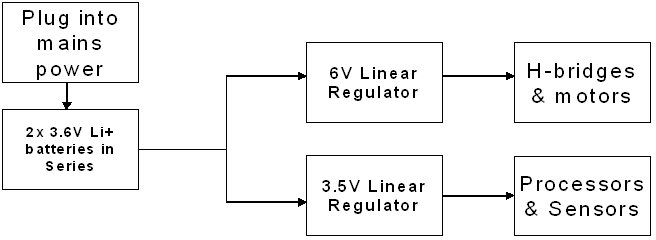 This is the basic outline of what we want to achieve. See how we have seperated the motor supply from the proccessors. This is because the motors can introduce noise which is in the form of voltage and current spikes. These spikes can seriously damage the more delicate processors. Next we need to take these components - the voltage regulators and the charging micro chips and turn our design concept into a schematic diagram.
 The two big yellow components are the charging micro chips. You can see they have a lot of inputs and outputs to make sure they won't blow up the batteries. There are two lots of two batteries, one set each charged seperately. Then on the right are some small yellow voltage regulators for 3.2V and 5V. The 6V system for the motors didn't need to be regualted in the end. So now all those little resistors and capacitors, inductors, diodes and microchips need to be 'placed' on an electrical design of the PCB, here's an image of what a 'footprint' for a microchip might look like;
 This particular footprint is designed for a 'quad flat package' micro chip which has 32 pins. The green rectangles will become solder pads on the PCB and the red lines are just guide marks. This particular chip is only a few milimetres across so you can imagine how tiny those solder pads are, and the hassle it would be if we got our dimensions even a little bit out!
So now you can see what I have been talking about when I say we had to find or design the correct footprint for every single component on the shematic. The computer will transfer those footprints onto the digital PCB and try to put lines that represent solder tracks between all the pins, but it can get very complicated and in the end we
had to opt for double sided boards. This means we can have solder tracks crossing each other by travelling onto the other side of the PCB first. It is much more complicated to manufacture a double sided board and in the end we may even have to go to a company who will do it for us. Here's a glimpse at what the finished design for the power supply PCB will look like:
 It doesn't make much sense does it? Well in the end it doesn't have to. This very image will be printed out onto basic transparent OHP plastic and placed on top of the blankboard. The board has a layer of conductive material across it. During the manufcturing process the board is bombarded with UV light except for the areas where the ink from the printed desgn halts the light. Then the plastic design is removed and the board is placed in an acid bath. The weakened metal will be eaten away and the protected metal remains, and there you have your tracks and pads, ready for soldering. Easy!
Hopefully the finished product will look something like this design:
Thursday, July 20, 2006
Hardware
Libramentum can be split into three basic hardware systems. Build, sensors and peripherals, and proccessing.
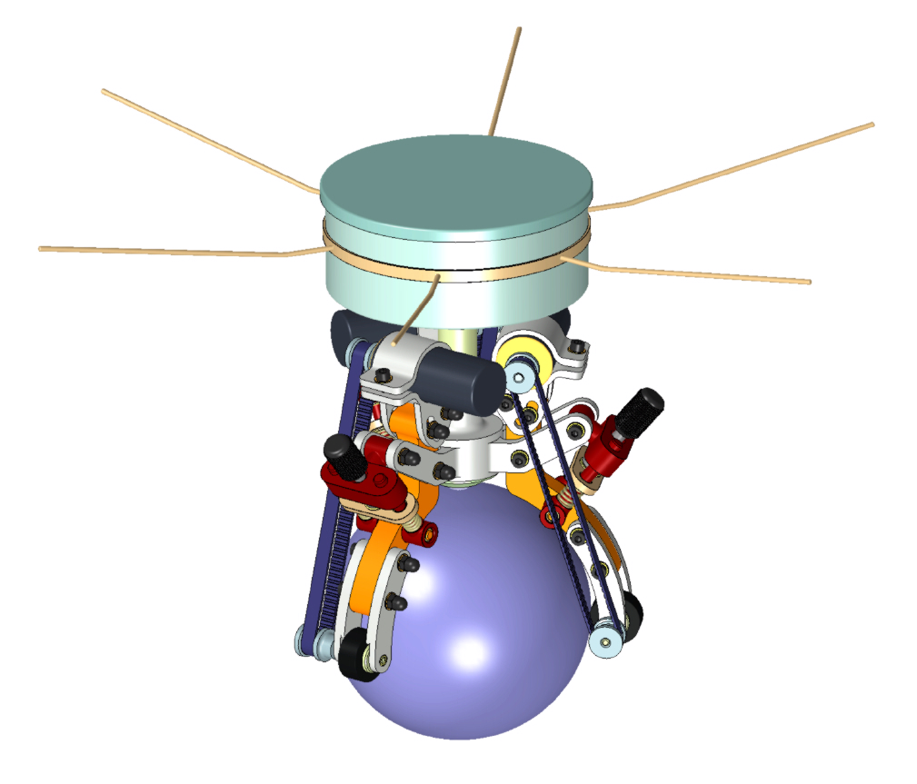
The physical build of our robot was designed by a german engineering exchange student. Though my lab partner and I had decided we wanted two motors driving the ball at ninety degrees to each other - similar to a mouse ball - our engineering student redesigned Libramentum to have three rollers at 120 degrees to each other.
With two rollers (90 degrees) there would always be a particular direction at which one of the rollers was doing no work, and in fact the friction of the ball rubbing across the unused roller would seriously distort our balancing calculations. The three-roller design (120 degrees) solved the problem by requiring all rollers to be driving the ball at all times. Therefore even though there would still be friction involved, it would be a more constant variable and easier to compensate for in the calculations.
Libramentum is not a large robot. There are pictures of other balancing robots on the net, and some of them are even as tall as a person! But Libramentum will be able to be placed on a table and should stand (once built) about 200-300mm high. The diametre of the ball is only 100mm! Most of the robot will be machined from aluminium with some parts being left in their 'rapid-prototyping' states. Rapid prototyping is a big 3-D printer. You can make a design on computer and the printer will construct it out of special powder and glues for you to see and test the design before making it out of a more expensive material.
The sensors will be placed at various points on the robot to assess where it is and what attitude it is in. To do this we need to be able to calculate Libramentum's angle of tilt to earth (attitude) and its position relative to other objects, or to its start point. Attitude is calculated using a small piezo-gyroscope and an accelerometer. The gyroscope uses oscillating vibrations to detect its movement relative to where it started, and an accelerometer detects the rate at which it is moving relative to gravitational pull. Because the robot can fall over the ball in any of 360 degrees, we need to have two sensing systems (two each of the acceleromter and gyro) each at ninety degrees to each other. Each set gives us accurate fall rates in each direction (the X and Y directions) and we can combine the two rates to calculate the real direction of fall - which will be a combination of the X and Y vectors.
The 'station-keeping' sensor is simply an optical sensor taken straight out of an optical mouse. It is mounted over the ball and takes pictures of the surface of the ball. The sensor then compares two pictures and works out how far the ball has moved in both X and Y directions then feeds that information back to the proccessors. This isn't much help when the robot is standing still trying to balance, but when it will be moving from place to place it will be using its own momentum as an aid to balancing and at that point the optical sensor will be able to tell us how fast Libramentum is travelling across the floor or the desk.
As well as the sensors are the motors and these will be controlled by the processors based on the information from the sensors. Each motor will be controlled individually - forward or backward - at a variable speed to get Libramentum upright again. The motors are situated near the top of the ball and belts run down the arms to the rollers which are postioned just under the equator. The arms provide the double purpose of holding the robot on top of the ball, and also providing the rollers to drive it.
The third part of the hardware is the electronics and processing. This is made up of two electronic printed circuit boards similar to what you would find in a computer, and a power supply board. The power supply is a rechargeable battery system which can provide the current and voltage for all the electronics and also a seperate and more powerful supply for the motors. The motors can draw a lot of current and they also introduce a lot of electrical noise which can fry an electronic chip. We don't want that! So it is important to keep them seperate.
The two proccessing boards are the motherboard and the daughterboard. The motherboard takes care of the sensors and peripherals. It receives the inputs from one gyro/accelerometer pair and combines it, recieves inputs from the other pair and combines it, then it sends these values to the daughterboard.
The daughterboard takes these rates of movement from the X and Y axis, and calculates in which direction the robot is falling over the ball and at what speed. Then it calculates which motors need to be driven in which direction and at what speed in order to get the robot back up on top of the ball again. It sends these values back to the motherboard which ensures the motors are provided with the correct voltages to do what they have to. The proccess repeats, and should catch the robot beginning to fall before it gets very far from top and centre.
Added to this the motherboard will read inputs from the optical sensor and send these to the daughterboard. The daughter board will assess if the ball has to be moved in a particular direction and command the mothorboard to move the motors as required.
You can see there are a lot of very high speed calculations that need to be done. The motherboard has three large proccessors designed to handle the sensor inputs and motor outputs, and the daughterboard has an even larger proccessor to handle all the calculations. The idea for us is to get Libramentum balancing. We will design the robot so that different types of daughterboards can be interchanged. This means other students can try their hands at writing code that will be more efficient and more able to balance Libramentum and in the future - command her to move in a particular direction via radio control or even bluetooth. Our supervisor even wants to use an FPGA daughterboard which is a revolutionary type of electronic processor which will quite literally be able to program itself into balancing the robot.
But we have to get there first :-)
The physical build of our robot was designed by a german engineering exchange student. Though my lab partner and I had decided we wanted two motors driving the ball at ninety degrees to each other - similar to a mouse ball - our engineering student redesigned Libramentum to have three rollers at 120 degrees to each other.
With two rollers (90 degrees) there would always be a particular direction at which one of the rollers was doing no work, and in fact the friction of the ball rubbing across the unused roller would seriously distort our balancing calculations. The three-roller design (120 degrees) solved the problem by requiring all rollers to be driving the ball at all times. Therefore even though there would still be friction involved, it would be a more constant variable and easier to compensate for in the calculations.
Libramentum is not a large robot. There are pictures of other balancing robots on the net, and some of them are even as tall as a person! But Libramentum will be able to be placed on a table and should stand (once built) about 200-300mm high. The diametre of the ball is only 100mm! Most of the robot will be machined from aluminium with some parts being left in their 'rapid-prototyping' states. Rapid prototyping is a big 3-D printer. You can make a design on computer and the printer will construct it out of special powder and glues for you to see and test the design before making it out of a more expensive material.
The sensors will be placed at various points on the robot to assess where it is and what attitude it is in. To do this we need to be able to calculate Libramentum's angle of tilt to earth (attitude) and its position relative to other objects, or to its start point. Attitude is calculated using a small piezo-gyroscope and an accelerometer. The gyroscope uses oscillating vibrations to detect its movement relative to where it started, and an accelerometer detects the rate at which it is moving relative to gravitational pull. Because the robot can fall over the ball in any of 360 degrees, we need to have two sensing systems (two each of the acceleromter and gyro) each at ninety degrees to each other. Each set gives us accurate fall rates in each direction (the X and Y directions) and we can combine the two rates to calculate the real direction of fall - which will be a combination of the X and Y vectors.
The 'station-keeping' sensor is simply an optical sensor taken straight out of an optical mouse. It is mounted over the ball and takes pictures of the surface of the ball. The sensor then compares two pictures and works out how far the ball has moved in both X and Y directions then feeds that information back to the proccessors. This isn't much help when the robot is standing still trying to balance, but when it will be moving from place to place it will be using its own momentum as an aid to balancing and at that point the optical sensor will be able to tell us how fast Libramentum is travelling across the floor or the desk.
As well as the sensors are the motors and these will be controlled by the processors based on the information from the sensors. Each motor will be controlled individually - forward or backward - at a variable speed to get Libramentum upright again. The motors are situated near the top of the ball and belts run down the arms to the rollers which are postioned just under the equator. The arms provide the double purpose of holding the robot on top of the ball, and also providing the rollers to drive it.
The third part of the hardware is the electronics and processing. This is made up of two electronic printed circuit boards similar to what you would find in a computer, and a power supply board. The power supply is a rechargeable battery system which can provide the current and voltage for all the electronics and also a seperate and more powerful supply for the motors. The motors can draw a lot of current and they also introduce a lot of electrical noise which can fry an electronic chip. We don't want that! So it is important to keep them seperate.
The two proccessing boards are the motherboard and the daughterboard. The motherboard takes care of the sensors and peripherals. It receives the inputs from one gyro/accelerometer pair and combines it, recieves inputs from the other pair and combines it, then it sends these values to the daughterboard.
The daughterboard takes these rates of movement from the X and Y axis, and calculates in which direction the robot is falling over the ball and at what speed. Then it calculates which motors need to be driven in which direction and at what speed in order to get the robot back up on top of the ball again. It sends these values back to the motherboard which ensures the motors are provided with the correct voltages to do what they have to. The proccess repeats, and should catch the robot beginning to fall before it gets very far from top and centre.
Added to this the motherboard will read inputs from the optical sensor and send these to the daughterboard. The daughter board will assess if the ball has to be moved in a particular direction and command the mothorboard to move the motors as required.
You can see there are a lot of very high speed calculations that need to be done. The motherboard has three large proccessors designed to handle the sensor inputs and motor outputs, and the daughterboard has an even larger proccessor to handle all the calculations. The idea for us is to get Libramentum balancing. We will design the robot so that different types of daughterboards can be interchanged. This means other students can try their hands at writing code that will be more efficient and more able to balance Libramentum and in the future - command her to move in a particular direction via radio control or even bluetooth. Our supervisor even wants to use an FPGA daughterboard which is a revolutionary type of electronic processor which will quite literally be able to program itself into balancing the robot.
But we have to get there first :-)
Beginnings
I'm starting this blog about 5 months into the project, and there are only 5 months left to go, but let me tell you about the robot I am making.
Name: Libramentum
Purpose: To balance on a ball, and use that ball as a 'wheel' for maneuvering
Design Conecept: Libramentum is being designed to provide a 'proccessor intensive' platform from which other students can design proccessing systems that will be more and more efficient at stabilising and driving the robot.
But what does this all mean?
Take a robot like R2D2. He's pretty cool right? He's solid and stable and he's not about to fall over just sitting there. But what happens when he does fall over? Now he's lying on his side and there is no way to get back onto his wheels again. What we are designing is a robot that is built onto a ball and it needs a comprehensive system to ensure that it doesn't fall over even when it's just standing still! The idea is similar to a Segway - but with an extra plane of freedom, and the robot will use a combination of accelerometers and gyroscopes along with steady drive motors and some heavy duty proccessing in order to remain upright.
The end result is a machine that will actually fight back when gravity tries to pull it to the ground - or when someone tries to knock it over. From there, the instructions required to drive Libramentum in a particular direction are calculated into the balancing routine.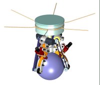 It sounds tricky, and it is. There are two of us working hard to get it built and running as well as our supervisor and another engineering student who has designed the build of the robot itself. And his supervisor. And an outside source for power supplies who helped us design a lightweight, high capacity rechargeable battery system similar to what you'd find in your mobile phone. So what have we done so far? I'll get you up to speed in the next installment but until then - watch this space!
Name: Libramentum
Purpose: To balance on a ball, and use that ball as a 'wheel' for maneuvering
Design Conecept: Libramentum is being designed to provide a 'proccessor intensive' platform from which other students can design proccessing systems that will be more and more efficient at stabilising and driving the robot.
But what does this all mean?
Take a robot like R2D2. He's pretty cool right? He's solid and stable and he's not about to fall over just sitting there. But what happens when he does fall over? Now he's lying on his side and there is no way to get back onto his wheels again. What we are designing is a robot that is built onto a ball and it needs a comprehensive system to ensure that it doesn't fall over even when it's just standing still! The idea is similar to a Segway - but with an extra plane of freedom, and the robot will use a combination of accelerometers and gyroscopes along with steady drive motors and some heavy duty proccessing in order to remain upright.
The end result is a machine that will actually fight back when gravity tries to pull it to the ground - or when someone tries to knock it over. From there, the instructions required to drive Libramentum in a particular direction are calculated into the balancing routine.
 It sounds tricky, and it is. There are two of us working hard to get it built and running as well as our supervisor and another engineering student who has designed the build of the robot itself. And his supervisor. And an outside source for power supplies who helped us design a lightweight, high capacity rechargeable battery system similar to what you'd find in your mobile phone. So what have we done so far? I'll get you up to speed in the next installment but until then - watch this space!
Subscribe to:
Posts (Atom)
